
PART 1: Servo Motor Control
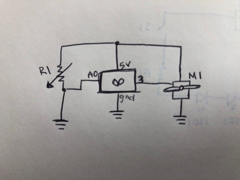
In this section of the lab, I followed the schematic below to create a circuit to control a servo motor. I used a slider potentiometer for analog input values and and connected this to the analog pin A0. I used the PWM pin 3 for the output of the motor.
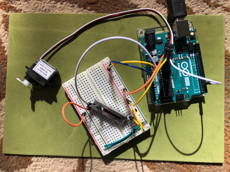
Below is the finished circuit and is connected to the Arduino.
I then wrote the code below to take the analog input and output through the motor. The potentiometer values needed to be mapped so that the motor would spin 180 degrees.
This file contains hidden or bidirectional Unicode text that may be interpreted or compiled differently than what appears below. To review, open the file in an editor that reveals hidden Unicode characters.
Learn more about bidirectional Unicode characters
| #include <Servo.h> | |
| Servo serv; | |
| int pot = A0; | |
| int servoPin = 3; | |
| void setup() | |
| { | |
| Serial.begin(9600); | |
| serv.attach(servoPin); | |
| } | |
| void loop() | |
| { | |
| int potVal = analogRead(pot); | |
| Serial.print("Potentiometer Value: "); | |
| Serial.println(potVal); | |
| delay(500); | |
| int angle = map(potVal, 0, 1023, 0, 179); | |
| serv.write(angle); | |
| } |
Below is the motor in action.
PART 2: DC Motor Control
For this portion of the lab I created the schematic below which consisted of a DC motor, the Arduino, a switch and an H-bridge.

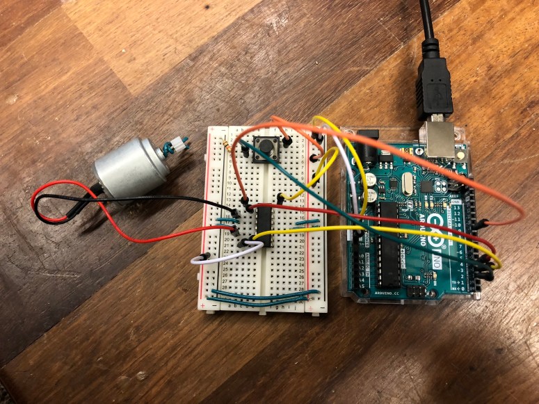
I followed the schematic above and the H-bridge instructions from the lab to create the circuit below.
I then created a code that would automatically have the motor spinning one direction when the switch was set to HIGH. When the switch was pressed and set to LOW, the motor would begin spinning in the opposite direction.
This file contains hidden or bidirectional Unicode text that may be interpreted or compiled differently than what appears below. To review, open the file in an editor that reveals hidden Unicode characters.
Learn more about bidirectional Unicode characters
| const int switchPin = 2; // switch input | |
| const int motor1Pin = 3; // H-bridge leg 1 (pin 2, 1A) | |
| const int motor2Pin = 4; // H-bridge leg 2 (pin 7, 2A) | |
| const int enablePin = 9; // H-bridge enable pin | |
| void setup() | |
| { | |
| pinMode(switchPin, INPUT); | |
| pinMode(motor1Pin, OUTPUT); | |
| pinMode(motor2Pin, OUTPUT); | |
| pinMode(enablePin, OUTPUT); | |
| digitalWrite(enablePin, HIGH); | |
| } | |
| void loop() | |
| { | |
| int switchVal = digitalRead(switchPin); | |
| if (switchVal == HIGH) | |
| { | |
| digitalWrite(motor1Pin, LOW); | |
| digitalWrite(motor2Pin, HIGH); | |
| } | |
| else | |
| { | |
| digitalWrite(motor1Pin, HIGH); | |
| digitalWrite(motor2Pin, LOW); | |
| } | |
| } |
Below is the DC motor switching directions based on the input of the switch.
PART 3: Stepper Motor Control
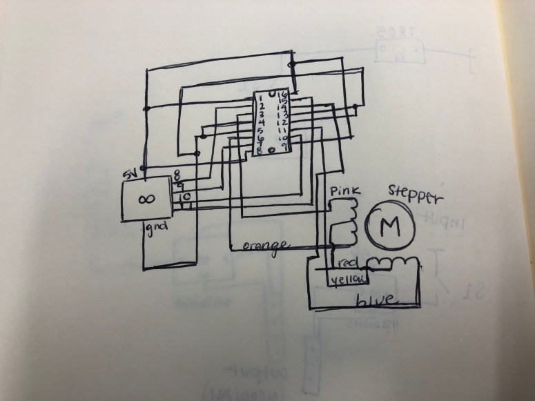
In this part of the lab, I drew the following schematic and set up the stepper motor with the Arduino. This circuit include that Arduino, H-bridge and a stepper motor.
I set up the circuit below according to the schematic and, again, following the H-bridge guidelines from the lab.
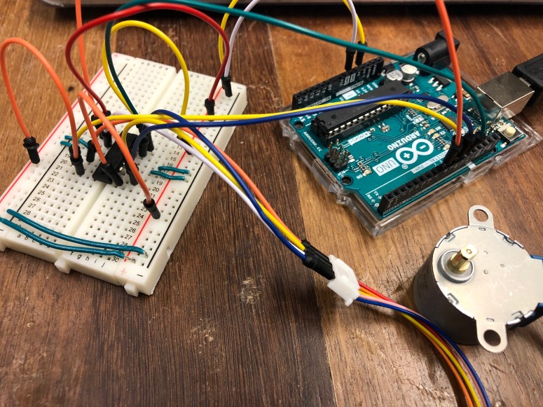
I then created code that tells the stepper motor to complete one full revolution, pause for 1000 ms, then complete one full revolution in the other direction.
This file contains hidden or bidirectional Unicode text that may be interpreted or compiled differently than what appears below. To review, open the file in an editor that reveals hidden Unicode characters.
Learn more about bidirectional Unicode characters
| #include <Stepper.h> | |
| const int stepsPerRevolution = 510; | |
| Stepper myStepper(stepsPerRevolution, 8, 9, 10, 11); | |
| void setup() | |
| { | |
| myStepper.setSpeed(60); | |
| Serial.begin(9600); | |
| } | |
| void loop() | |
| { | |
| Serial.println("Clockwise"); | |
| myStepper.step(stepsPerRevolution); | |
| delay(1000); | |
| Serial.println("Counterclockwise"); | |
| myStepper.step(-stepsPerRevolution); | |
| delay(1000); | |
| } |
Below is the stepper motor in action.
