PART 1: Variable Input & Output:
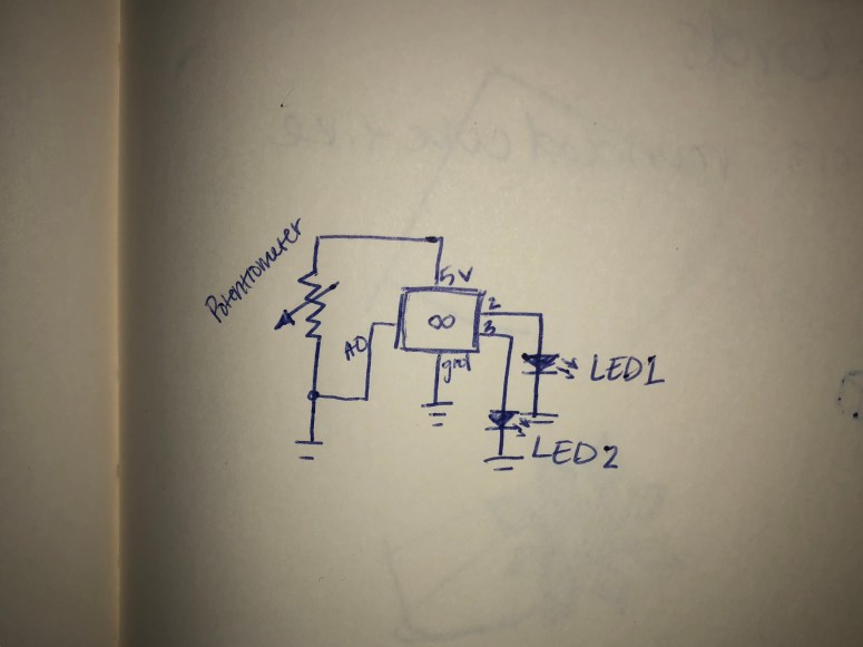
I began this section by building the circuit with a potentiometer and two yellow LEDs. After creating a schematic, I built the circuit and programed the Arduino so that the different LEDs would light up depending on the reading from the potentiometer.
Below is a picture of the schematic I used to build the circuit.
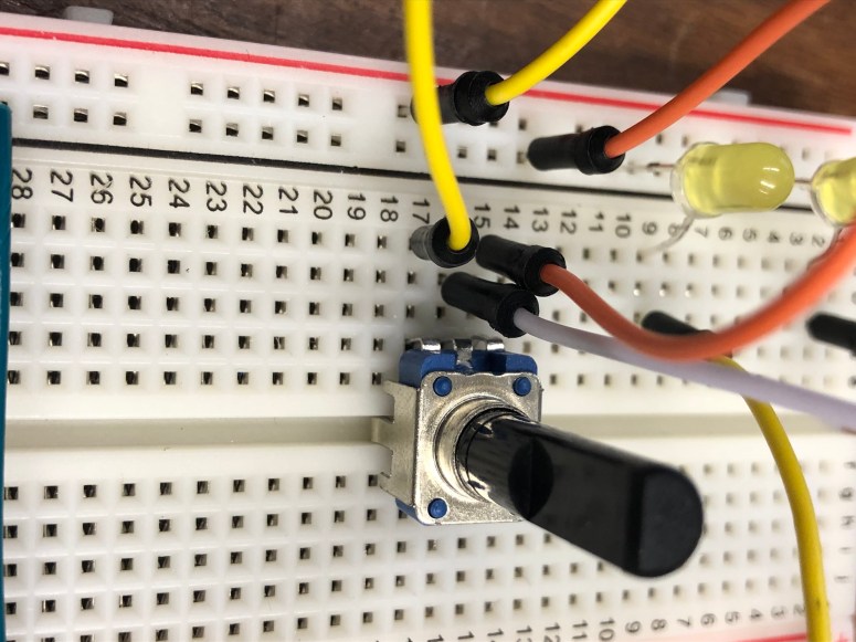
Below is a picture of the potentiometer and LEDs used in the circuit.
Below is the code I entered into Arduino to get the potentiometer to turn each LED on depending on the analog input received.
This file contains hidden or bidirectional Unicode text that may be interpreted or compiled differently than what appears below. To review, open the file in an editor that reveals hidden Unicode characters.
Learn more about bidirectional Unicode characters
| int pot = A0; | |
| int LED1 = 2; | |
| int LED2 = 3; | |
| int mappedVal; | |
| void setup() | |
| { | |
| Serial.begin(9600); | |
| pinMode(LED1, OUTPUT); | |
| pinMode(LED2, OUTPUT); | |
| } | |
| void loop() | |
| { | |
| int potVal = analogRead(pot); | |
| mappedVal = map(potVal, 0, 1023, 0, 3); | |
| if (mappedVal <= 1) | |
| { | |
| digitalWrite(LED1, HIGH); | |
| digitalWrite(LED2, LOW); | |
| } | |
| else if (mappedVal > 1) | |
| { | |
| digitalWrite(LED1, LOW); | |
| digitalWrite(LED2, HIGH); | |
| } | |
| } |
Below is a video of the potentiometer in action, lighting one LED or the other based on the analog values it received from me turning the switch.
PART 2: Tone Output:
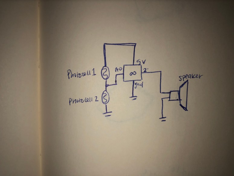
In this section, I began by drawing a schematic. Then I soldered wires to the speaker and I created the circuit. I programed Arduino so that when I covered one photocell, the tone played by the speaker would be at one frequency and when I covered the other photocell, the tone was played at a different frequency.
Below is a schematic I used to build the circuit.
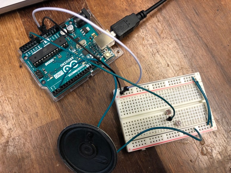
Below is the speaker circuit connected the Arduino.
Below is the code I entered into Arduino to get the speaker to play different frequencies depending on the analog input received from the photocells.
This file contains hidden or bidirectional Unicode text that may be interpreted or compiled differently than what appears below. To review, open the file in an editor that reveals hidden Unicode characters.
Learn more about bidirectional Unicode characters
| int photoCell = A0; | |
| int sensorReading; | |
| float freqVal; | |
| int speaker = 2; | |
| void setup() | |
| { | |
| Serial.begin(9600); | |
| pinMode(speaker, OUTPUT); | |
| } | |
| void loop() | |
| { | |
| int photoVal = analogRead(photoCell); | |
| sensorReading = photoVal; | |
| Serial.print("Sensor Reading: "); | |
| Serial.println(sensorReading); | |
| delay(500); | |
| freqVal = map(sensorReading, 0, 1023, 100, 1000); | |
| if (sensorReading <= 512) | |
| { | |
| tone(speaker, freqVal); | |
| } | |
| else | |
| { | |
| tone(speaker, freqVal); | |
| } | |
| } |
Below is the speaker in action, changing tones bases on the analog input received from the photocells.
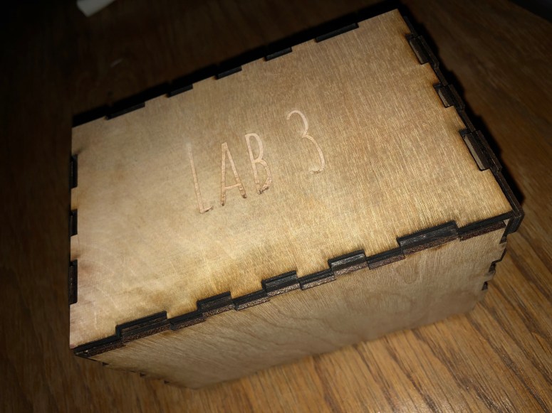
PART 3: Laser Cut Sensor Box:
I began this part of the lab by creating a box in MakerCase. I then brought it over to Illustrator and made sure it fit all the laser requirements. I also added in some text to show that the enclosure was created for Lab 3. It was created for the photocell/speaker circuit. The circuit goes inside and if the lid is removed, the tone changes.