
Part 1: Soldered Breakout Board
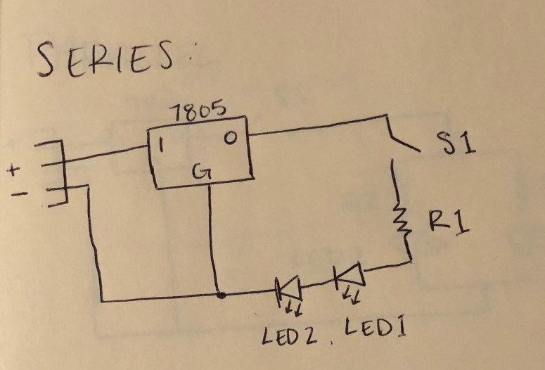
For part one of the lab, I chose to do the series circuit from lab 1. Below is a photo of all the parts laid in their positions on the breakout board.

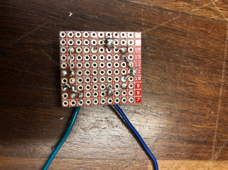
Below is the backside of the breakout board, completely soldered in place.
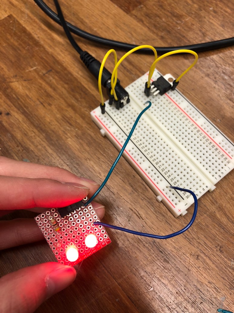
Below is the breakout board connected to the breadboard, where the LEDs are lit up by the switch.
Part 2: Digital Input and Output
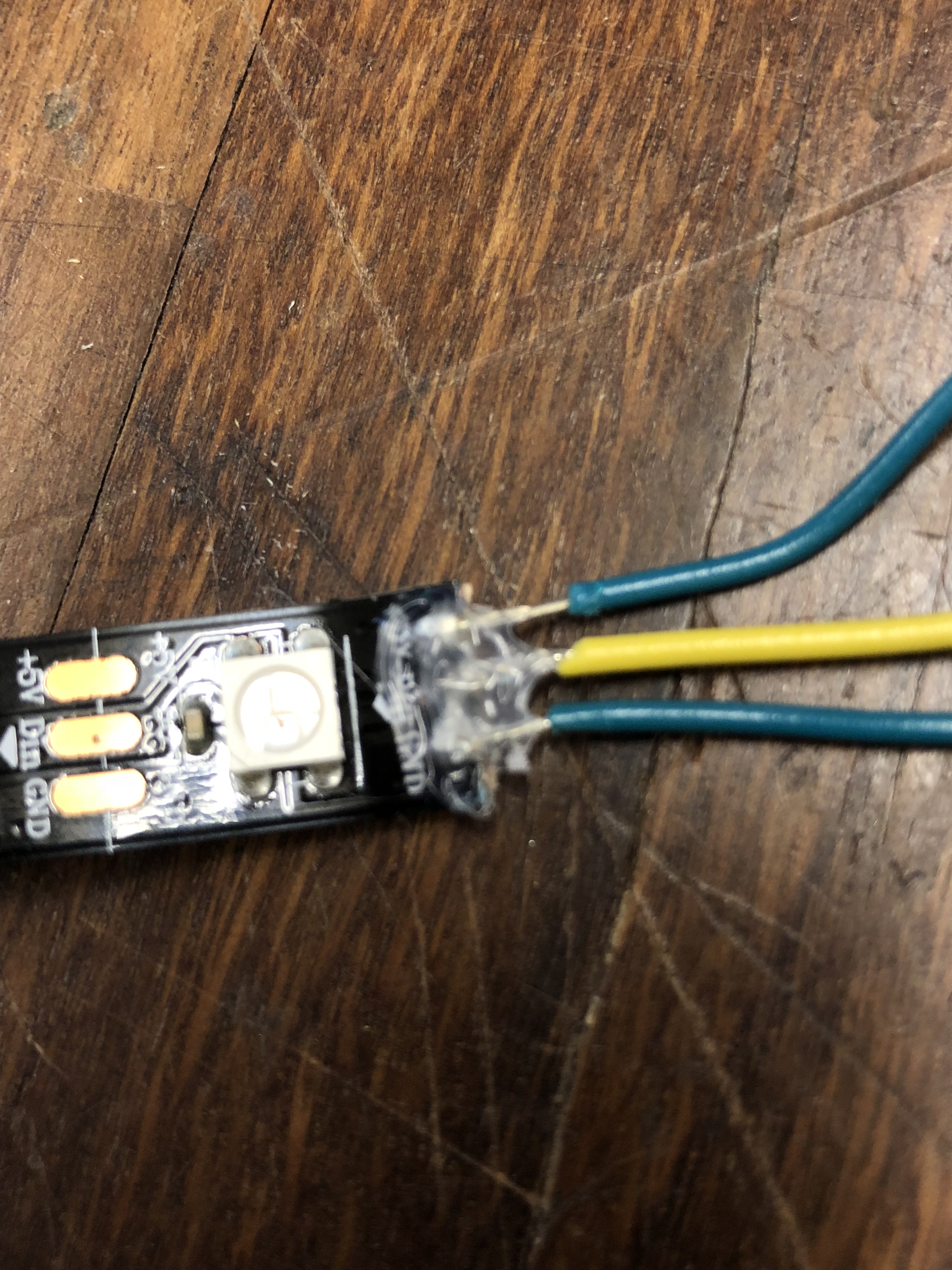
For part two, I began by soldering wires to the neopixel, as shown below.
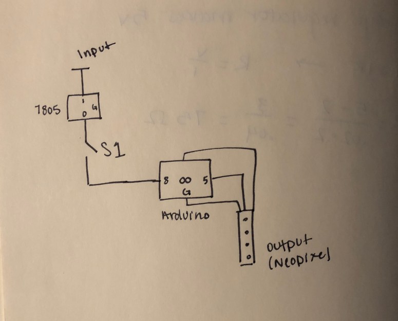
Then I created a circuit with a switch button on the breadboard and connected the neopixel to the arduino.
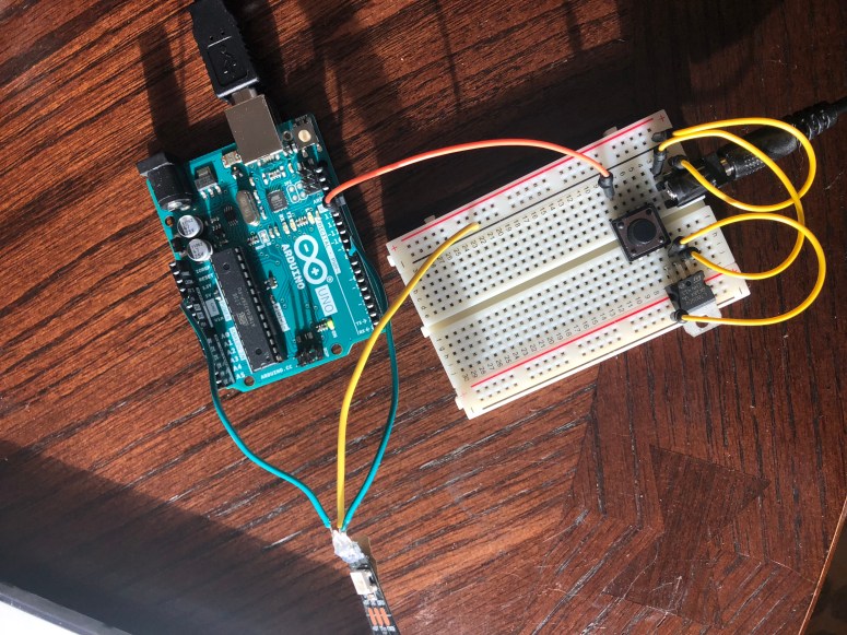
I then added the following code to arduino, which allowed the neopixel to flash when the switch was pressed.
(Still working on embedding the code and video).
| #include <Adafruit_NeoPixel.h> | |
| void setup() { | |
| pinMode(8, OUTPUT); | |
| } | |
| void loop() { | |
| digitalWrite(8, HIGH); | |
| delay(500); | |
| digitalWrite(8, LOW); | |
| delay(500); | |
| } |
