PART 1: LEDs in Series and Parallel
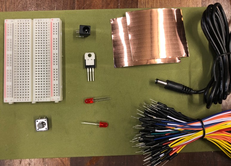
For part 1, I started this lab off by laying out all the necessary materials, including a power source, breadboard, voltage regulator, switch, LEDs and wires.
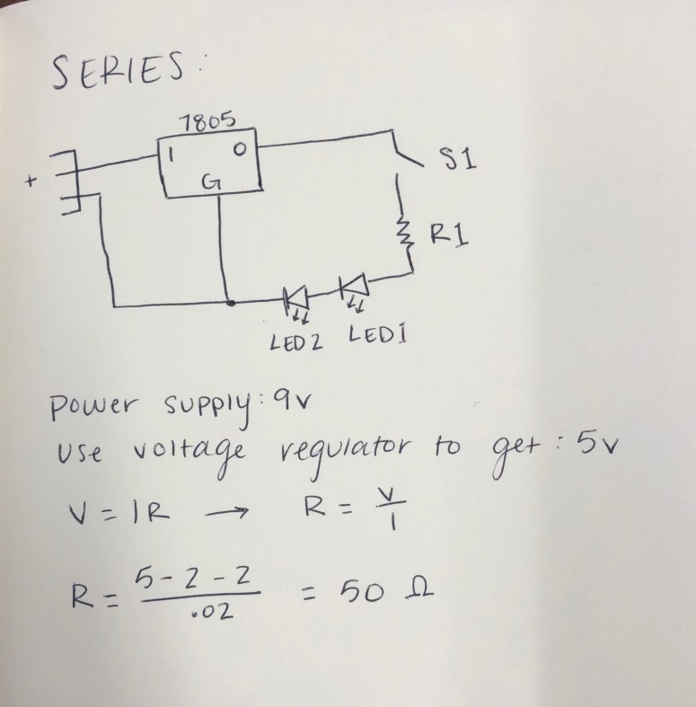
I then began by drawing out the schematic for a series circuit. This schematic includes the voltage regulator, a switch, a resistor and two 2V LEDs. I then used Ohm’s Law to calculate the appropriate resistance required and got the matching resistor. In this case I used a 47 ohm resistor as it was the closest available. I also accommodated for the voltage regulator, as the power source is 9V and we wanted to use 5V.
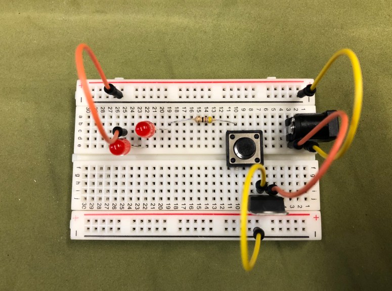
Below is the finished series circuit.
Below is the finished series circuit in action.

I then began the construction of the parallel circuit with the schematic drawing. This circuit includes the voltage regulator, a switch, two resistors and two LEDs. Again, I calculated the necessary resistance required for the circuit and grabbed those resistors. In this case, I used 100 ohm resistors as they were the closest available.
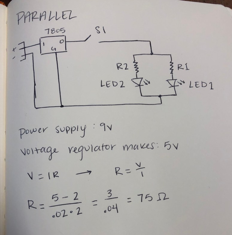
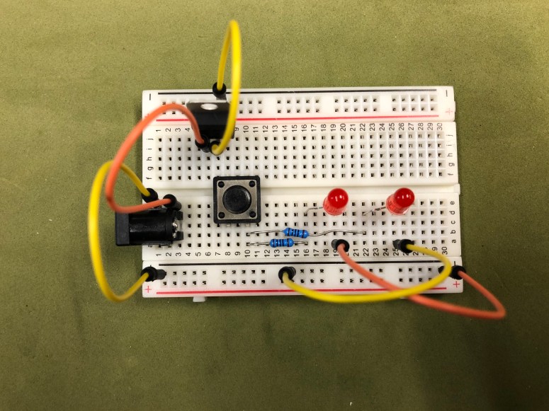
Below is the finished parallel circuit.
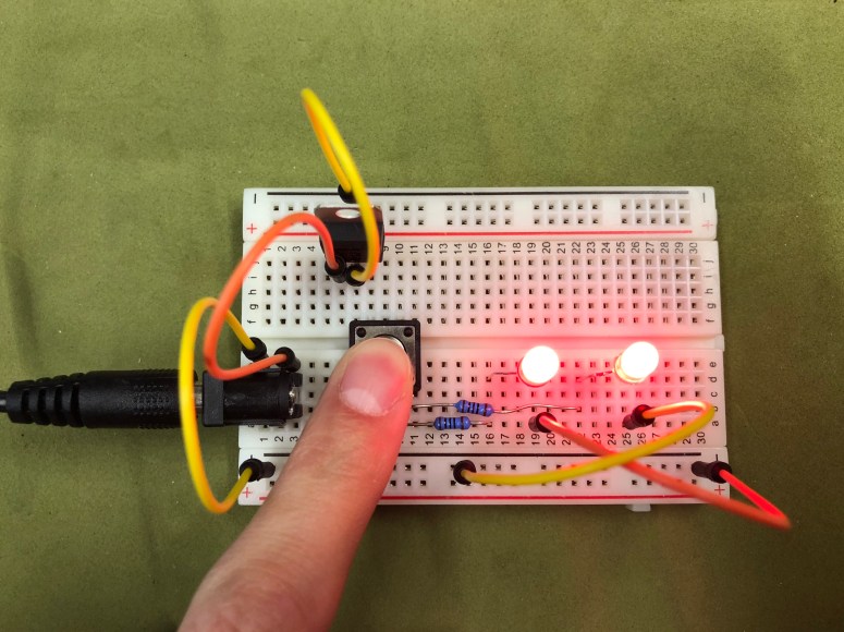
Below is the finished parallel circuit in action.
PART 2: DIY Switch
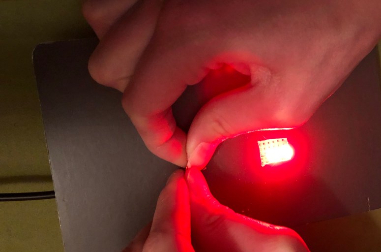
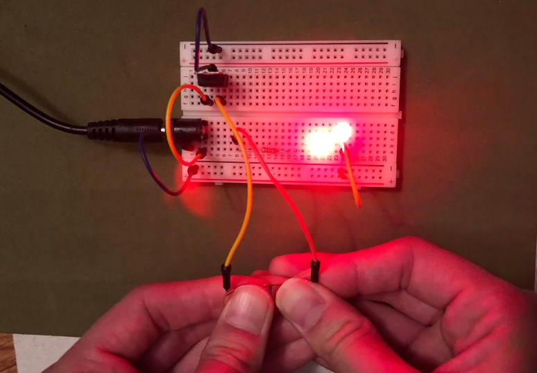
For part 2, I used copper tape to create a homemade switch. The tape itself is conductive and when pressed together, with a good enough seal, the circuit will work.
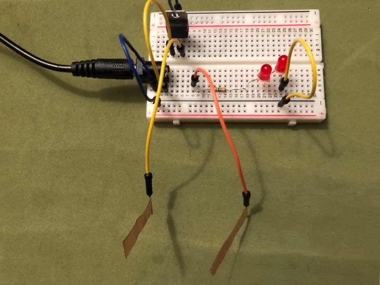
Below is a photo of me pressing the tape together to allow the LEDs to light up.
PART 3: Creative Enclosure
For part three, I wanted to create a simple enclosure that would hide all the electronics beneath with an obvious use of the switch above. I used cardboard to cut out a small sections for the switch and the LEDs.
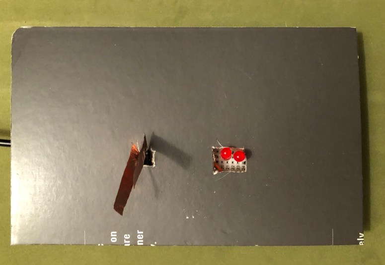
Below is the creative enclosure in use.